This article was prepared with AI assistance based on an analysis of the current Lumina Studio source code, existing Wiki content, and relevant workflows. It has been checked against the current version, but omissions or details that become outdated may remain as the software evolves. If you find an error or have a clearer explanation, example, or suggestion, please leave a comment on this page or propose an edit on GitHub.
How Should I Set Backing, Colour Layers, and Layer-Height Modifiers?
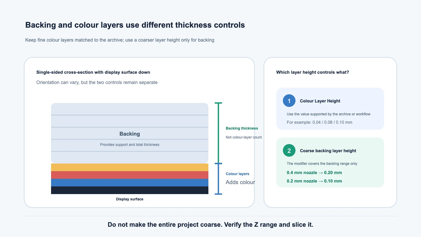
If you remember only one rule: backing thickness, Colour Layer Height, and the global slicer layer height are not the same setting.
- Colour Layer Height controls how each layer contributes to the colour recipe. It must match a value supported by the current Material Archives, Inferred LUT, or Legacy LUT.
- Backing Thickness controls structural support and total thickness. It is not a count of colour layers.
- Backing Layer Height Modifier applies a coarser layer height only to the backing range, reducing the number of backing layers.
- Lumina uses 0.20 mm for a 0.4 mm nozzle and 0.10 mm for a 0.2 mm nozzle in that backing range.
- After Generate, open the complete project, slice it, turn to the display surface, and inspect the real layers.
Four concepts that are easy to confuse
| Term | What it controls | Most direct effect |
|---|---|---|
| Backing | The structural section behind the colour stack | Strength, total thickness, material use, and print time |
| Backing Thickness | The physical thickness of that backing section | Backing layer count and total model thickness |
| Colour Layers | Thin layers that combine to form the visible colour | Colour, light transmission, and detail |
| Colour Layer Height | The thickness of each colour-producing layer | Recipe behaviour, accumulated colour, and Z detail |
A model can use 0.08 mm colour layers with a 1.6 mm backing. The 1.6 mm value is the total backing thickness. It does not mean that every layer becomes 1.6 mm, nor that the model contains twenty colour layers.
The display surface may face the build plate or sit above the backing, depending on the workflow. That changes the Z order, but it does not merge the two settings.
Why not make the whole project 0.20 mm?
A layered colour recipe is calibrated for particular materials, layer heights, and layer counts. If a recipe expects 0.08 mm colour layers and the entire project is changed to 0.20 mm, each layer becomes thicker, light transmission changes, colour accumulation changes, and the slicer may no longer produce the expected stack.
The backing does not perform the same colour-mixing job. It can therefore use a coarser local layer height while the display layers remain fine. That is the sole purpose of the modifier: fine colour layers, coarse backing layers.
What does the Backing Layer Height Modifier do?
When a compatible Bambu-family slicer is selected in Settings and the modifier is enabled, Lumina writes a height range into the generated 3MF:
- 0.4 mm nozzle: 0.20 mm layers inside the backing range;
- 0.2 mm nozzle: 0.10 mm layers inside the backing range;
- colour layers keep the fine height required by the current source and workflow.
The setting is enabled by default, saved automatically, and shown only for a compatible slicer selection. It does not change Backing Thickness. It prints the same backing range with fewer, thicker layers.
Other slicers may ignore this project metadata or use a different local-parameter system. No error message does not prove that the modifier was applied.
Set it in Lumina Studio
- Open Settings.
- Select the slicer, printer, and nozzle you actually use.
- If Backing Layer Height Modifier is available, decide whether it is appropriate for this workflow.
- Return to Converter and set Backing Thickness for the model.
- Choose Colour Layers and Colour Layer Height supported by the selected archives or LUT.
- create a new Preview and Generate a new 3MF.
Do not change Backing Thickness, Colour Layer Height, Colour Layers, and the slicer’s global layer height at the same time. If the result changes, you will not know which setting caused it.
Verify the modifier range after opening the project
Open Lumina’s complete 3MF as a project. Importing only its geometry can discard project filaments, object relationships, or the height range.
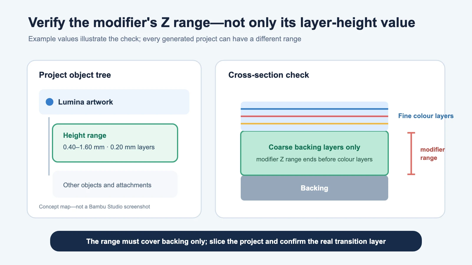
Expand the model in the slicer’s object tree. When the modifier has been preserved, you should see a distinct height range. The numbers depend on the generated model; do not copy a range from another project.
Confirm all three points:
- the range exists and covers the backing’s real Z interval;
- the local height matches the nozzle—0.20 mm for 0.4 mm, or 0.10 mm for 0.2 mm;
- the range does not include any fine colour layer.
If the range is absent, check the selected slicer, the modifier switch, and whether the 3MF was opened as a complete project. Do not replace it with a coarse modifier covering the entire object.
Real slicing is mandatory
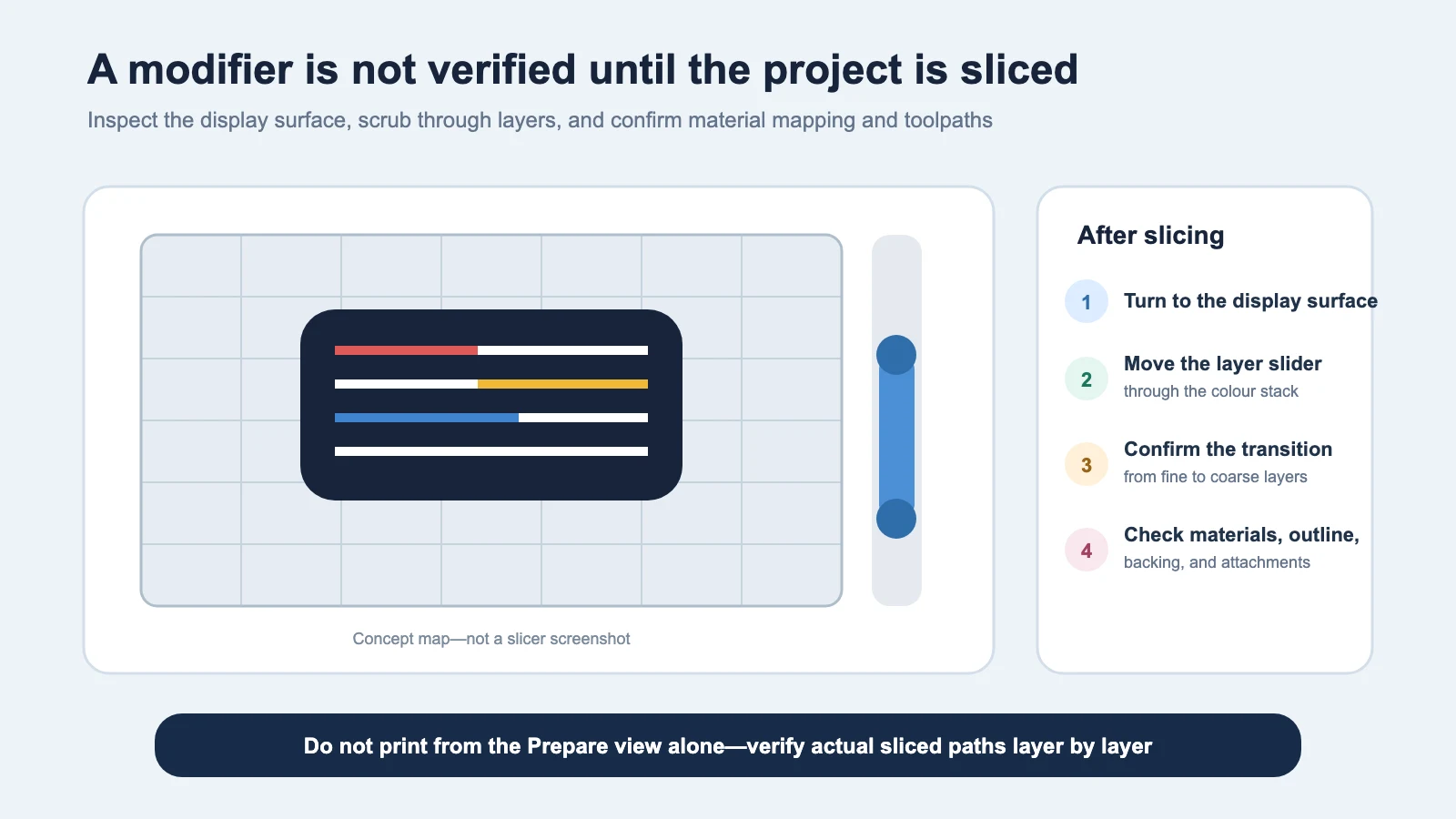
Seeing a modifier in Prepare view does not prove that the final toolpaths are right. Run Slice, enter Preview, and then:
- turn the model to its actual display surface;
- move the layer slider through the colour stack;
- verify the transition from fine colour layers to coarse backing layers;
- inspect backing, outline, coating, Free Color, and other attachments for overlap;
- confirm that project filaments still map to the intended physical spools.
For the complete object and material check, see Import a Lumina 3MF into Your Slicer Correctly.
Separate Backing is not the layer-height modifier
Both names mention the backing, but they solve different problems:
- Separate Backing exports the backing as an independent object for selection, material assignment, or further editing in the slicer.
- Backing Layer Height Modifier keeps the same object structure and assigns a coarser height only to the backing’s Z range.
One option does not enable the other. Use both only when you need both behaviours, and verify the sliced result.
Workflows that require extra care
Gradient cards
Gradient cards have a fixed layer structure, object-colour mapping, and print method. Do not add the ordinary backing modifier. Follow Generate and Print Gradient Calibration Cards.
Puzzle and other specialised exports
Specialised structures can manage their own slicing data. Do not add a duplicate height range merely to reproduce a familiar 0.20 mm value.
Double-sided or complex structures
With colour structures on both faces, or backing interleaved with recesses and attachments, names alone cannot identify a safe coarse range. Inspect every layer. If the modifier touches either display surface, disable it and Generate again, or use a separately verified slicer-native method.
Non-compatible slicers
If the slicer does not show the local range, do not assume it worked. Use that slicer’s native local-parameter feature and inspect the resulting layers.
Common questions
Why does the process header still say 0.08 mm when the backing is 0.20 mm?
The header usually shows the base process height, while the backing uses a local object range. Inspect the object tree and sliced layers, not only the header value.
I selected 0.04 mm. Why do I also see 0.08 mm or 0.20 mm?
You may be looking at three different values: Colour Layer Height, the process base height, and the backing’s local height. Confirm which one is shown and whether the current archive or LUT supports 0.04 mm. If the data, selection, and toolpaths disagree, do not print.
Can I make every colour layer 0.20 mm to save more time?
Not as a general shortcut. The existing recipe may no longer be valid. Use a new colour-layer height only when the current data source explicitly supports it and a test print has passed.
Should a 0.2 mm nozzle use 0.20 mm backing layers?
No. Lumina’s automatic rule uses half the nozzle diameter: 0.10 mm for a 0.2 mm nozzle.
Why is the modifier missing from Settings?
It is shown only when a compatible Bambu-family slicer is selected. For another slicer, verify whether it offers an equivalent local height-range feature.
Can I increase the backing height further if the estimate is still long?
Do not increase it from time alone. Local layer height is constrained by nozzle, line width, material, and slicer rules. First prove that the modifier is active and that backing is the real bottleneck, then test any additional change on a sample.
Content licence
Unless otherwise noted, the original text and concept diagrams on this page are available under the Wiki’s CC BY-NC-SA 4.0 content licence. Third-party slicer names and trademarks belong to their respective owners.
Lumina Studio and slicers continue to change. Treat the current interface and the actual sliced toolpaths as the final authority.
Submit feedback
Your feedback is sent privately to the Wiki maintainers and is not displayed publicly on this page.