This article was prepared with AI assistance based on an analysis of the current Lumina Studio source code, existing Wiki content, and relevant workflows. It has been checked against the current version, but omissions or details that become outdated may remain as the software evolves. If you find an error or have a clearer explanation, example, or suggestion, please leave a comment on this page or propose an edit on GitHub.
Large Format: Tile Size, Assembly Order, and ZIP Files
Large Format divides one finished artwork into adjacent tiles, generates a separate 3MF for every tile, and packages the results in a ZIP. It is intended for wall art, signs, display panels, and other work larger than one usable build plate.
Remember these rules:
- Width and Height describe the assembled artwork; Tile Width and Tile Height are maximum dimensions for one generated part;
- filenames run from top to bottom and left to right:
R1C1is the upper-left tile; - the last row or column is often smaller than the maximum tile size;
- tiles are adjacent and non-overlapping. Lumina does not add joints, locating holes, overlap, or assembly clearance;
- Preview checks the complete artwork, not physical seams or real bed placement;
- after download, open every 3MF in the slicer and verify size, direction, materials, and toolpaths before printing.
The real example below uses a finished size of 450×300 mm and a tile limit of
180×180 mm. Lumina generated a 3×2 set of six 3MF files.
When should I use Large Format?
Use it when:
- the complete artwork exceeds the printer’s usable bed area;
- every tile should share one colour source, structure, and colour-layer height;
- you can align and secure the printed pieces manually;
- you are prepared to slice, label, and inspect every tile separately.
Do not use it when each part needs different materials or structure, or when you expect automatic puzzle joints or alignment hardware. First prove the image, colours, and basic structure with an ordinary single-image project.
Step 1: enter the assembled size
Upload the image, choose the colour source, and enter the final Width or Height. With aspect ratio locked, the other value follows the source image.
This is the size after assembly, not the size of one tile. If the composition or orientation is wrong, prepare the source first; do not use tiling to stretch the artwork. See Upload, Replace, Crop, and Rotate an Image.
Step 2: enable Large Format and set tile limits
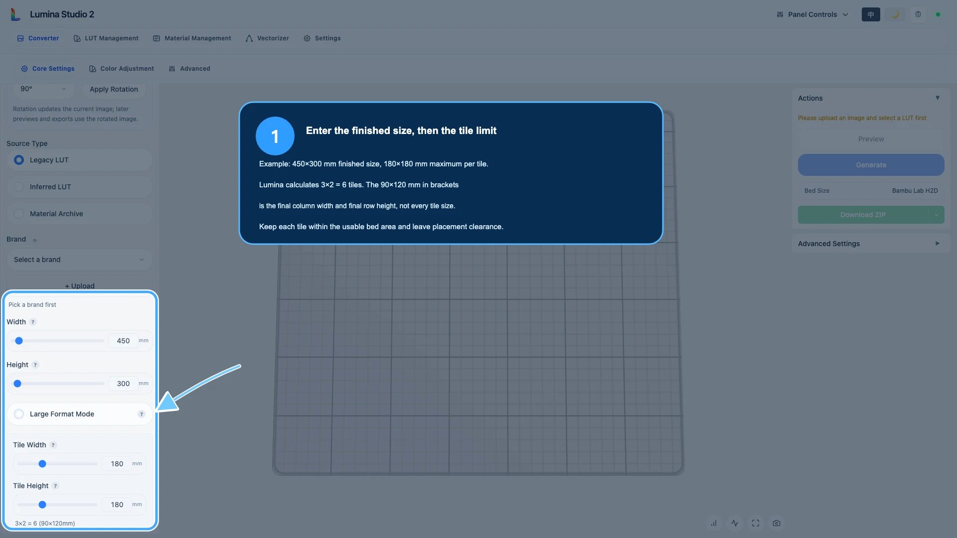
Enable Large Format Mode, then set Tile Width and Tile Height. These are maximums, not guaranteed dimensions for every part.
For this example:
- finished size:
450×300 mm; - maximum tile:
180×180 mm; - columns:
ceil(450 ÷ 180) = 3; - rows:
ceil(300 ÷ 180) = 2; - total:
3 × 2 = 6tiles.
The interface shows 3×2 = 6 (90×120mm). The value in brackets is the remaining width
of the last column and remaining height of the last row. It does not mean all six tiles
are 90×120 mm.
| Tile position | Actual size |
|---|---|
| R1C1, R1C2 | 180×180 mm |
| R1C3 | 90×180 mm |
| R2C1, R2C2 | 180×120 mm |
| R2C3 | 90×120 mm |
Set tile limits from the printer’s usable bed area, not only its advertised size. Leave room for excluded zones, Brim, purge or wipe areas, clips, and slicer-added geometry. Confirm a safe size in the real slicer first.
Step 3: read the coordinate map
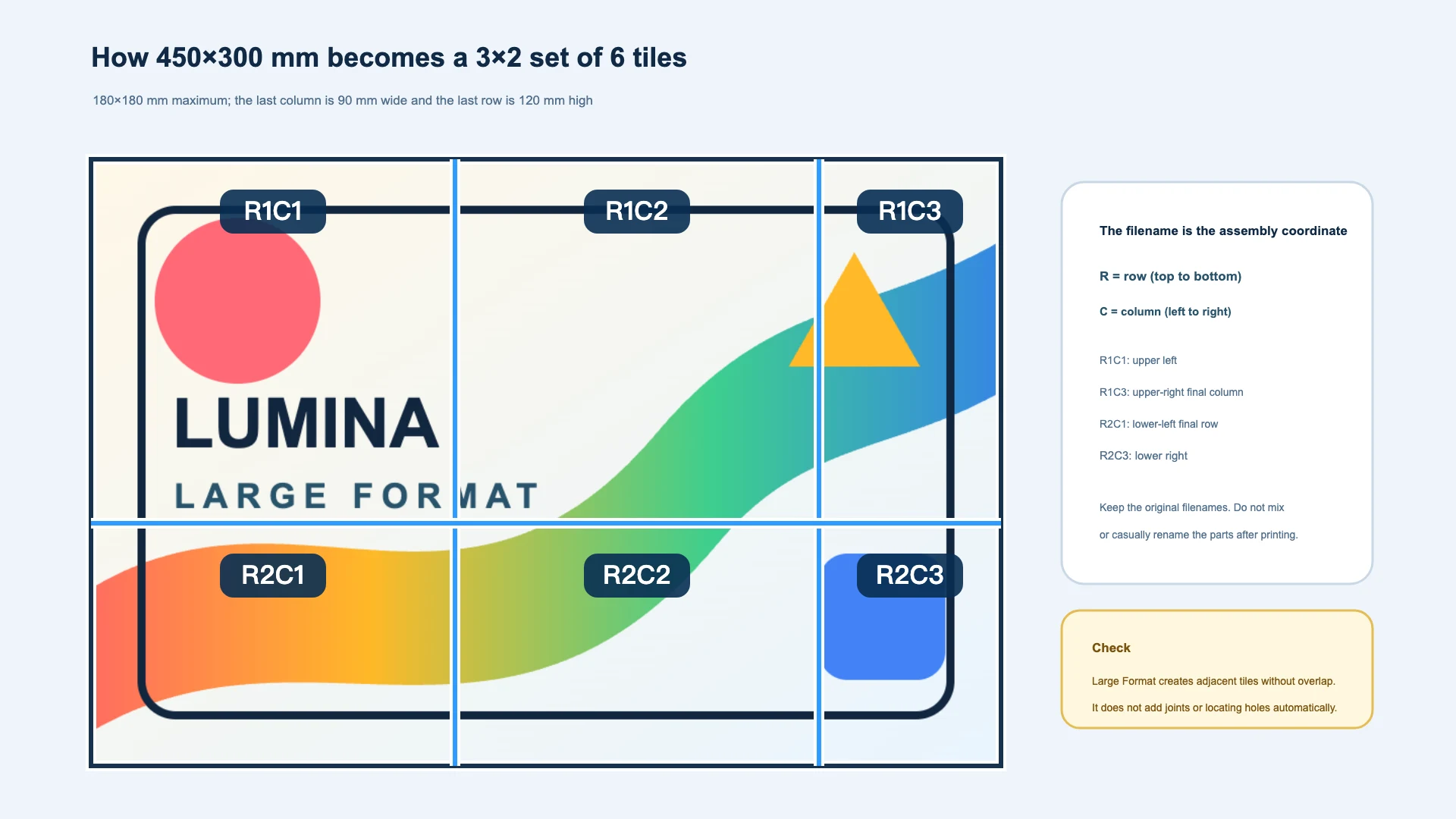
Rmeans row and increases from top to bottom;Cmeans column and increases from left to right;R1C1is the upper-left corner;R2C3is the lower-right corner in this example.
Keep the generated filenames. After printing, label the back of each part or its storage bag with the coordinate. Renaming similar pieces without a record makes orientation and assembly unnecessarily difficult.
Large Format cuts along adjacent boundaries. It does not create overlap, registration pins, puzzle tabs, adhesive gaps, or shrinkage compensation. Add and test those features in the source design or an external modelling tool when required.
Step 4: Preview the complete artwork
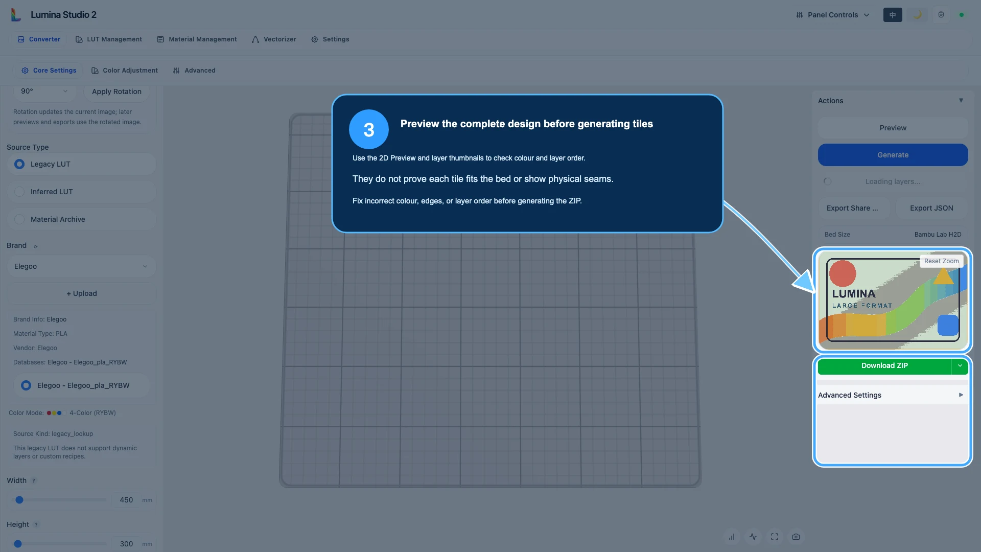
Run Preview and check:
- orientation, aspect ratio, and visible boundary;
- colour source and intended filaments;
- missing colours, broken edges, or incorrect transparency;
- Layer Preview order and colour-layer count;
- outline, backing, and other enabled structure.
This Preview describes the whole artwork. It does not show six separate build plates, physical seams, or whether a tile fits the selected printer. Fix colour, edge, or layer problems before generating the ZIP.
For the roles of Lumina Preview, slicer Preview, and the physical print, see Why Lumina Preview, Slicer Preview, and the Print Differ.
Step 5: Generate once and save the ZIP
Select Generate once and wait for all tiles. Do not repeatedly select the button, refresh, or replace the image while generation is running.
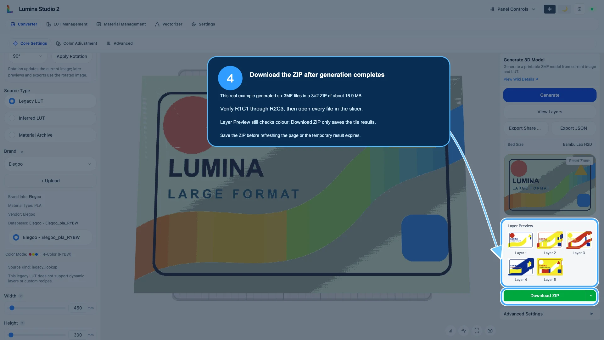
The verified example returned six files in a ZIP of about 16.9 MB:
large-format-demo_R1C1.3mf
large-format-demo_R1C2.3mf
large-format-demo_R1C3.3mf
large-format-demo_R2C1.3mf
large-format-demo_R2C2.3mf
large-format-demo_R2C3.3mf
Immediately verify that:
- file count matches the tile count;
- coordinates cover the complete grid;
- no file is empty or unreadable;
- the ZIP and extracted files are saved outside the temporary browser result.
Generated download links are not permanent storage. Save the ZIP before refreshing, starting a new task, or waiting for the temporary result to expire.
Step 6: inspect every tile in the slicer
Open each 3MF as a complete project and check:
- millimetre dimensions against the tile table;
- placement inside the usable bed area;
- display face, backing, and rotation;
- printer, nozzle, layer height, and real filament mapping;
- continuous colour toolpaths and no missing thin walls;
- Brim, outline, or support that might alter a seam edge.
Use one printer profile, nozzle, layer height, filament batch, and orientation wherever possible. Bed texture, material state, shrinkage, and manual alignment can still create visible seams even when digital boundaries are adjacent.
For material mapping, see Import a Lumina 3MF into the Slicer Correctly.
Step 7: dry-fit before permanent assembly
Arrange the first row from R1C1 to the right, then continue with the next row. Confirm
orientation and image continuity before using a backboard, fixture, tape, adhesive, or
mechanical fastener. Start from one reference corner and progress row by row so alignment
error does not accumulate in several directions.
The correct fixing method depends on material, backing thickness, environment, load, and service life. Test adhesion and safety for the real installation.
Common questions
Why is the last tile only 90×120 mm?
Because 180×180 mm is a maximum. After two 180 mm columns, 90 mm of the 450 mm width remains; after one 180 mm row, 120 mm of the 300 mm height remains.
Can all tiles have exactly the same dimensions?
Yes, if both finished dimensions divide evenly by the chosen tile limits. You may also add deliberate margin in the source design, but do not distort the artwork merely to make the numbers tidy.
Does Lumina add overlap or locating features?
No. Design overlap, cutting allowance, locating holes, or joints before Large Format and include their footprint in bed-fit calculations.
Preview looks correct. Why does one tile exceed the bed?
The full-image Preview is not a real slicer layout. Reduce the tile limit or reposition the object after considering excluded zones, Brim, and printer profile rules.
One 3MF will not open. Must I redo every tile?
Keep the downloaded ZIP and all readable files, then generate the same task again. If the same coordinate fails repeatedly, inspect that region for tiny geometry or unsupported SVG features. See Slicer Detection and 3MF Open Troubleshooting.
Image notes and content licence
The interface screenshots are real captures of the current English Lumina Studio build. The coordinate map is a clearly labelled concept diagram based on the verified 450×300 mm test. Focus frames and arrows explain existing controls; they do not invent interface state.
Unless otherwise noted, the original text, test artwork, calculations, and annotations are available under the Wiki’s CC BY-NC-SA 4.0 content licence. Third-party printer and slicer names belong to their respective owners.
Large Format compatibility and control names can change. Treat the current interface, downloaded ZIP, slicer result, and physical dry-fit as the final authority.
Submit feedback
Your feedback is sent privately to the Wiki maintainers and is not displayed publicly on this page.