This article was prepared with AI assistance based on an analysis of the current Lumina Studio source code, existing Wiki content, and relevant workflows. It has been checked against the current version, but omissions or details that become outdated may remain as the software evolves. If you find an error or have a clearer explanation, example, or suggestion, please leave a comment on this page or propose an edit on GitHub.
Base Plate Infill
Base plate infill controls the sparse infill density deeper inside the base plate. A lower value can reduce material use and print time; at 100%, the base is solid. This setting does not change the base plate thickness or turn the colour layers into sparse infill.
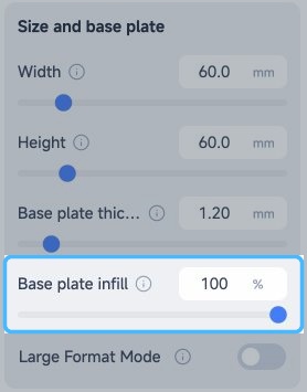
Find it in the Converter's basic settings, directly below Base plate thickness. The current range is 5%–100%, with a default of 100%. The slider moves in 5% steps; you can also enter any whole number within the range in the field on the right.
Why does a lower setting still produce a solid base?
To protect the appearance of each viewing surface, Lumina keeps 3 mm of the base plate solid, measured from the boundary between the colour layers and the base. Double-sided work has one protected region on each side. The colour layers themselves also remain solid.
As a result, when the generated base is no thicker than 3 mm, a single-sided base lies entirely inside the protected region. For double-sided work, a base no thicker than 6 mm has overlapping or touching protected regions and also remains solid. The exported project uses 100% infill for that base even if the slider is set lower.
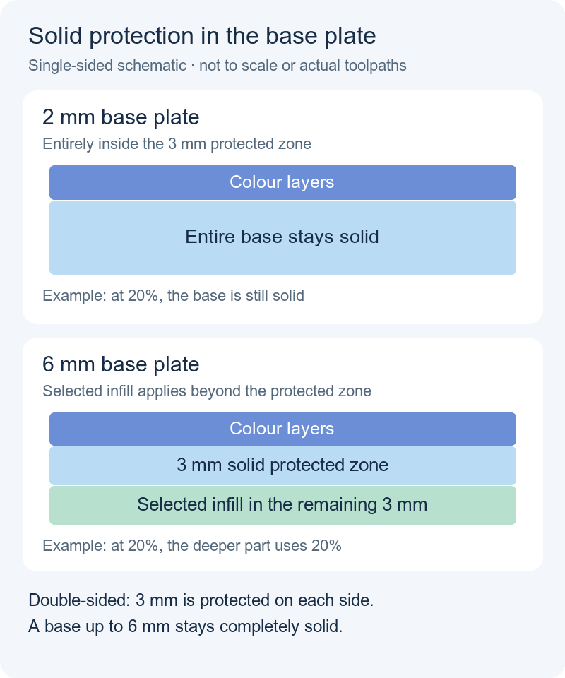
Schematic, not a slicer preview. The colours distinguish regions and do not represent toolpaths.
For example, with the slider set to 20%:
| Artwork | Generated base thickness | Exported infill settings |
|---|---|---|
| Single-sided | 1.20 mm | The entire base stays solid |
| Single-sided | 4.00 mm | 3 mm next to the colour layers stays solid; the deeper section uses 20% sparse infill |
| Double-sided | 6.00 mm | The protected regions meet, so the entire base stays solid |
| Double-sided | 8.00 mm | 3 mm on each side stays solid; the middle section uses 20% sparse infill |
The comparison uses the base thickness after layer-height adjustment when the model is generated, not the total model height including colour layers. Near the boundary, check the actual generated height and sliced preview.
A slicing comparison
We used Lumina's 3MF exporter to make a 20 × 20 mm single-sided test block, exported it at 20% and 100% infill, and sliced both in Bambu Studio. With a 2 mm base, the estimated material use was the same. With a 6 mm base, the 20% project had sparser internal paths and a lower material estimate.
This was a single-colour test model, not a physical print. Results also depend on the base dimensions, wall settings, and slicer configuration.
Check the result in your slicer
- Set Base Plate Thickness and Base plate infill for your artwork, then generate a new 3MF.
- Open the 3MF as a complete project in a slicer that supports its project settings, rather than importing only its geometry.
- Slice the project and move the layer slider through the base to inspect its internal paths. The outside surface alone does not show the infill.
- To compare settings, keep everything else unchanged, generate and slice a separate project for each value, then compare the internal paths, material estimates, and print times.
The slicer's top, bottom, and wall settings also affect the final paths. Slicers may read 3MF project settings differently, so check the actual sliced preview.
When is the control unavailable?
The control is disabled while Model Texture or Relief is enabled; some messages still call Model Texture “Model Surface”. Flat puzzles are not disabled by those two options. The backing layer-height modifier controls layer height, not infill density. See Backing, Colour Layers, and Layer-Height Modifiers for the difference.
Submit feedback
Your feedback is sent privately to the Wiki maintainers and is not displayed publicly on this page.