Slicer Guide
AI translation notice: This English tutorial was translated from the original Chinese tutorial with AI assistance. The screenshots are shared with the Chinese tutorial and show Bambu Studio in Simplified Chinese. The English setting names below follow Bambu Studio's official English interface.
Recent Lumina Studio versions support multiple slicers and printer profiles, so a downloaded project can normally be opened directly in your slicer. Use this guide to restore the settings if a project opens without its original process parameters.
Bambu Studio
Step 1: Select the printer and 0.08 mm process preset
Open Bambu Studio and select the printer profile that matches your machine. Under Process, choose the matching 0.08 mm preset, such as 0.08 mm High Quality when that preset is available for your printer.
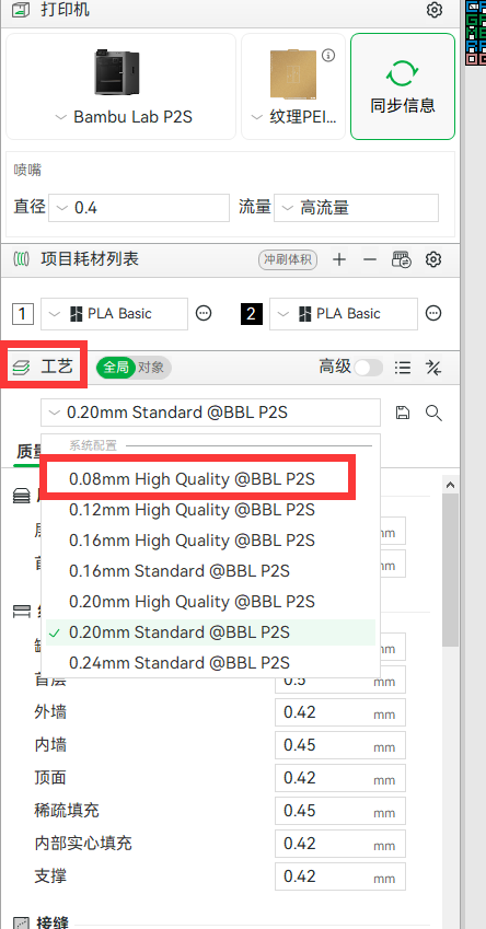
Step 2: Set the layer heights and initial-layer line width
Under Quality, set:
- Layer height: 0.08 mm
- Initial layer height: 0.08 mm
- Under Line width, Initial layer: 0.42 mm for the 0.4 mm nozzle shown in this example

Step 3: Adjust elephant-foot compensation and the wall generator
Set Elephant foot compensation to 0 mm. This helps prevent color from the second layer showing through the display surface; if that effect does not matter for your print, you may keep your usual value.
Set Wall generator to Arachne so the slicer can use variable-width walls.
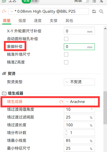
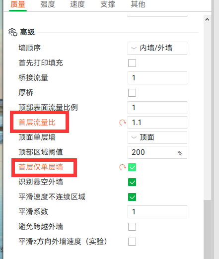
Step 4: Set the initial-layer flow and use one wall
Set Initial layer flow ratio to 1.1 as a starting value. You may tune this value for your own printer and material.
Enable Only one wall on first layer.
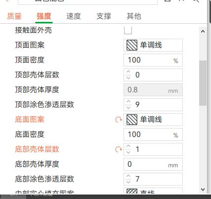
Step 5: Configure shells and surface patterns
Under Strength, set:
- Wall loops: 1
- Top shell layers: 0
- Bottom shell layers: 1
- Top surface pattern: Monotonic line
- Bottom surface pattern: Monotonic line
Setting Top shell layers to 0 is optional. The source workflow uses it to reduce crossing toolpaths that can form unwanted marks on the card.
Step 6: Configure infill
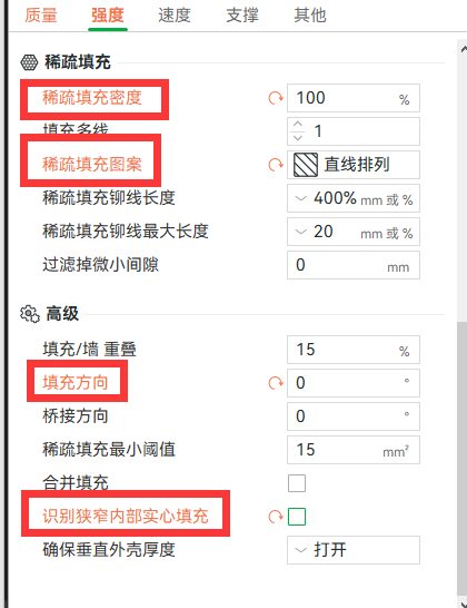
Still under Strength, set:
- Sparse infill density: 100%
- Sparse infill pattern: Aligned Rectilinear; Rectilinear is also acceptable
- Infill direction: 0°; 45° is an alternative
- Detect narrow internal solid infill: disabled
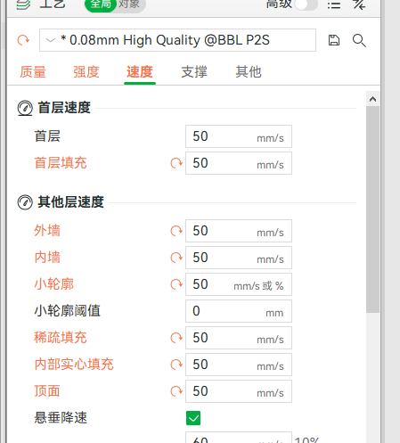
Step 7: Use a conservative speed
The source tutorial recommends lower speeds to reduce problems caused by printing too quickly. For the speed fields shown below, 50 mm/s is the suggested starting point. Increase the values only after confirming that your printer produces a clean result.
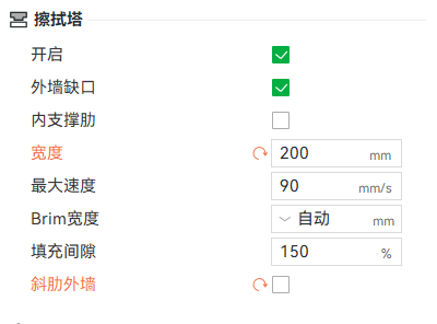
Step 8: Reshape the prime tower if needed
Under Prime tower, disable Rib wall. You can then change the tower's Width. The source workflow uses a large width value so the sliced prime tower becomes long and narrow, which can save space on the build plate.
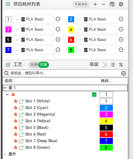
Step 9: Check filament and object mapping
This step is mainly for correcting object colors when the mapping is wrong. First check that the filament list uses the colors from the mode selected when the project was generated.
If the objects below use the wrong colors, which is more common when a model is imported instead of opened as a project, select each object and assign the intended filament.
The red and magenta modes reuse one object name, while the blue and cyan modes reuse another. For example, if you selected an RYBW preset but the generated object name says magenta, treat that object as red. Apply the same rule to blue and cyan, and verify the final assignments in the sliced preview.
After completing the settings and checking the mapping, slice the project. Review the layers and color changes in Preview before sending the job to your printer.
OrcaSlicer, ElegooSlicer, Snapmaker Orca, AnycubicSlicer Next, and compatible slicers
The current source tutorial provides detailed screenshots for Bambu Studio only. In another compatible slicer, apply the equivalent settings where they are available, and confirm the result in the sliced preview. Setting names and locations may differ between slicers and versions.
Advanced workflow: put the color surface on top
A textured PEI build plate can leave a pattern on the bottom surface of a gradient card or printed artwork. If that texture interferes with the intended appearance, you can flip the model so its color surface prints on top. This requires a small parameter change.
Step 1: Change the initial layer height
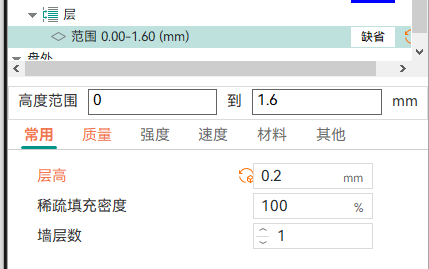
In the gradient-card example, the backing plate is 1.6 mm thick. After flipping the model, the white backing occupies the 0–1.6 mm height range. Set Initial layer height to 0.2 mm.

Step 2: Add a height range modifier
Right-click the model and choose Height range Modifier. Set the modifier range to 0–1.6 mm, then set Layer height within that range to 0.2 mm.
Step 3: Verify the five color layers
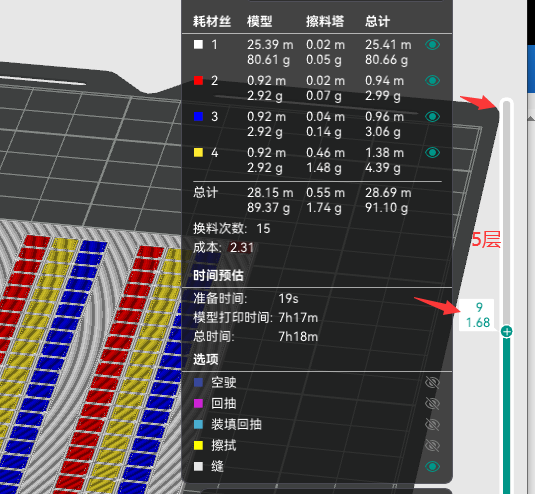
Slice the model and inspect the top of the preview. The uppermost five layers should be the color layers. If you see four or six color layers instead, recheck the initial-layer and height-range settings.
Other outline topics
The Chinese source currently lists transparent layers, relief 2.5D, and box workflows as outline topics but does not provide procedures for them. This English page does not add unverified steps.
Submit feedback
Your feedback is sent privately to the Wiki maintainers and is not displayed publicly on this page.