Open a Lumina 3MF in Your Slicer: Objects, Colours, and AMS Slots
AI translation notice: This English tutorial was translated from the reviewed Chinese source with AI assistance. The annotation text was also localized with AI assistance. The underlying Bambu Studio screenshots are real and shared with the Chinese tutorial; some interface labels therefore remain in Simplified Chinese. If any wording is unclear, please check the Chinese source or leave a comment.
After Lumina Studio finishes generating a project, the colour shown on the model is not the only thing that decides which spool prints each region. The slicer's project-filament list, every object's filament assignment, the physical spools loaded in the printer, and the AMS or external-spool positions must all correspond correctly.
This tutorial shows how to open a Lumina-generated 3MF as a complete project, inspect the object and filament mapping, and use a real sliced preview to check the display surface for wrong colours, missing layers, or lost details.
The examples use common Bambu Studio and OrcaSlicer workflows. Button locations can vary slightly between releases, but the checking order is the same.
Before you begin
Prepare the following:
- The complete 3MF generated and downloaded from Lumina Studio.
- The printer and nozzle you actually use.
- Every physical filament required by the artwork.
- If you use an AMS, ACE, MMU, or another multi-material system, a record of the slot that currently holds each spool.
If someone else supplied the 3MF, first confirm which Lumina version, filament profiles, and generation settings they used. A detached STL normally cannot retain the complete relationship between objects and filaments.
Step 1: Open the 3MF as a complete project
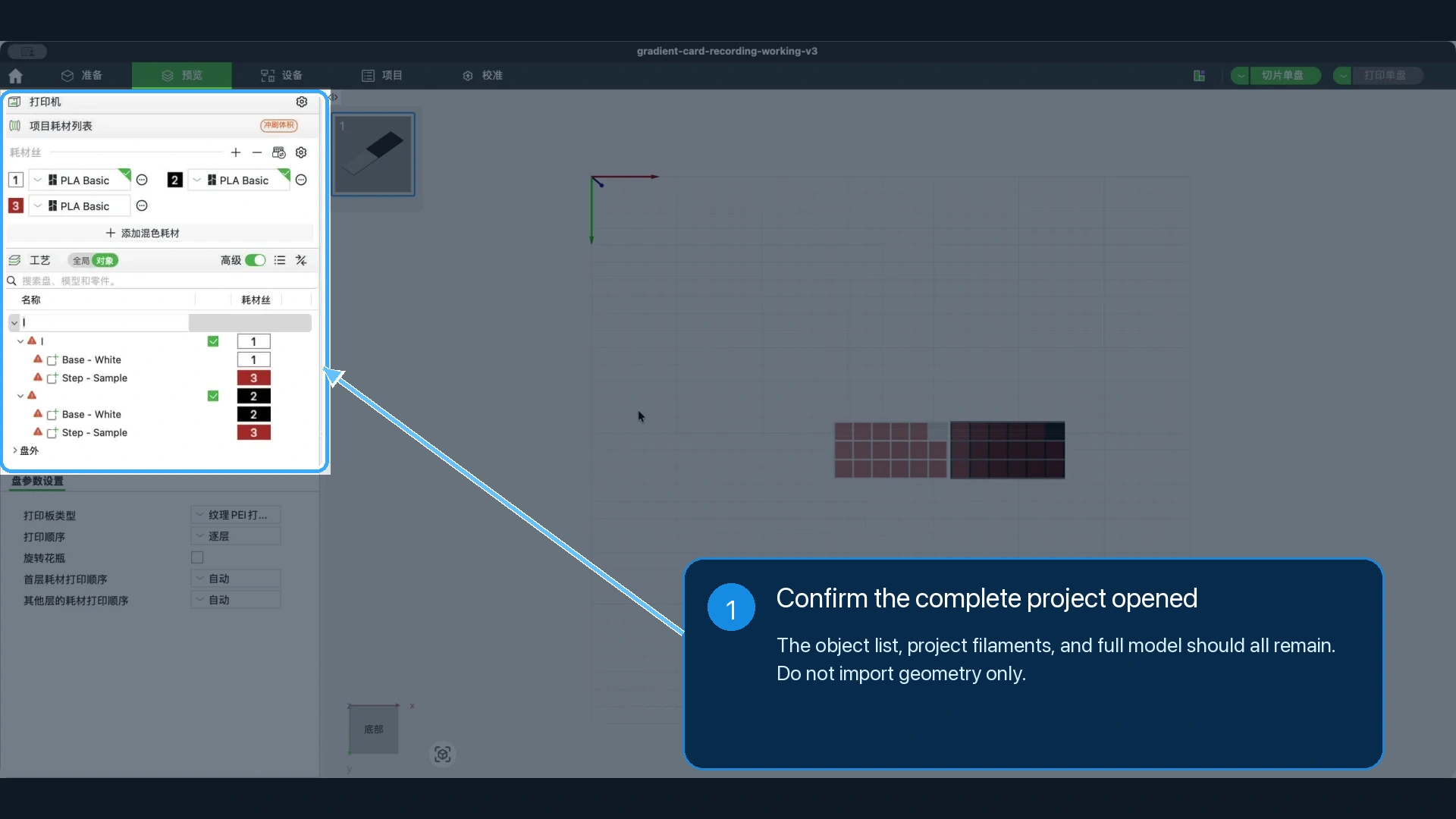
Open Bambu Studio or OrcaSlicer and use Open Project to load the 3MF generated by Lumina. You can also double-click the 3MF and select the slicer you normally use.
If the slicer asks whether to open the file as a project or import only the model or geometry, open the complete project. Importing geometry only can keep the shape while losing the original plate layout, object groups, filament numbers, or some project settings.
Before synchronising any material system, recolouring an object, or starting a print, confirm that you can see:
- One or more build plates.
- The models, objects, and parts in the object panel.
- A numbered set of project filaments.
- The complete model shape on the plate.
If the project opens as one merged model and the expected colour regions cannot be expanded in the object list, close it and reopen the original 3MF with Open Project.
Step 2: Check the printer and nozzle
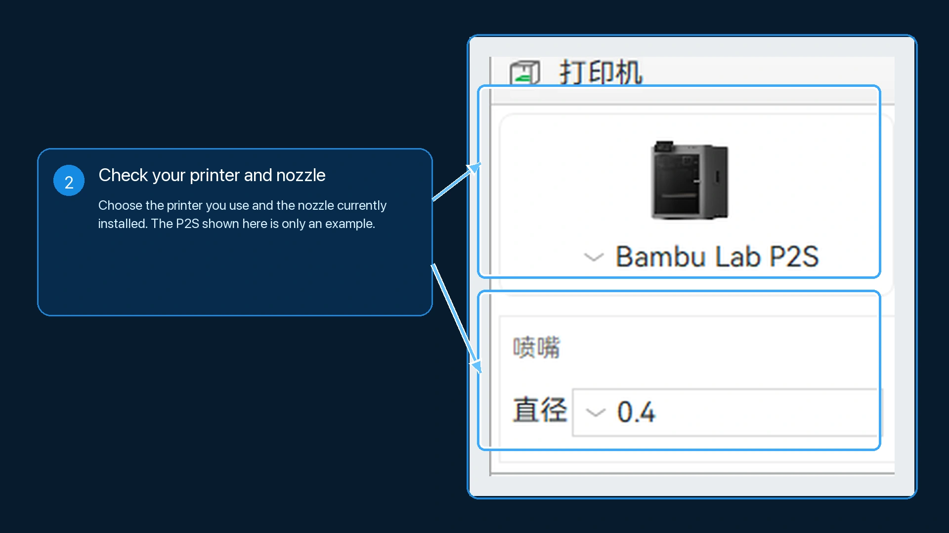
In the printer area, confirm that the selected profile matches the printer you actually use. Then confirm that the nozzle diameter matches the nozzle currently installed on that machine.
If the slicer reports that the original project is incompatible with the current printer or nozzle, do not overwrite every setting just to remove the warning. Check these possibilities first:
- The printer or nozzle selected in Lumina was incorrect.
- The required printer preset is missing from this slicer installation.
- The 3MF was generated for a different machine configuration.
If Lumina used the wrong device settings, the safest solution is to return to Lumina Studio, select the slicer, printer, and nozzle you actually use, and generate the project again. This is more reliable than guessing and rebuilding every project setting inside the slicer.
If you intentionally move the project to a compatible printer, recheck the filaments, layer height, printable area, and sliced preview after switching. A model remaining visible on the plate does not prove that the migrated project is ready.
Step 3: Keep four different kinds of information separate
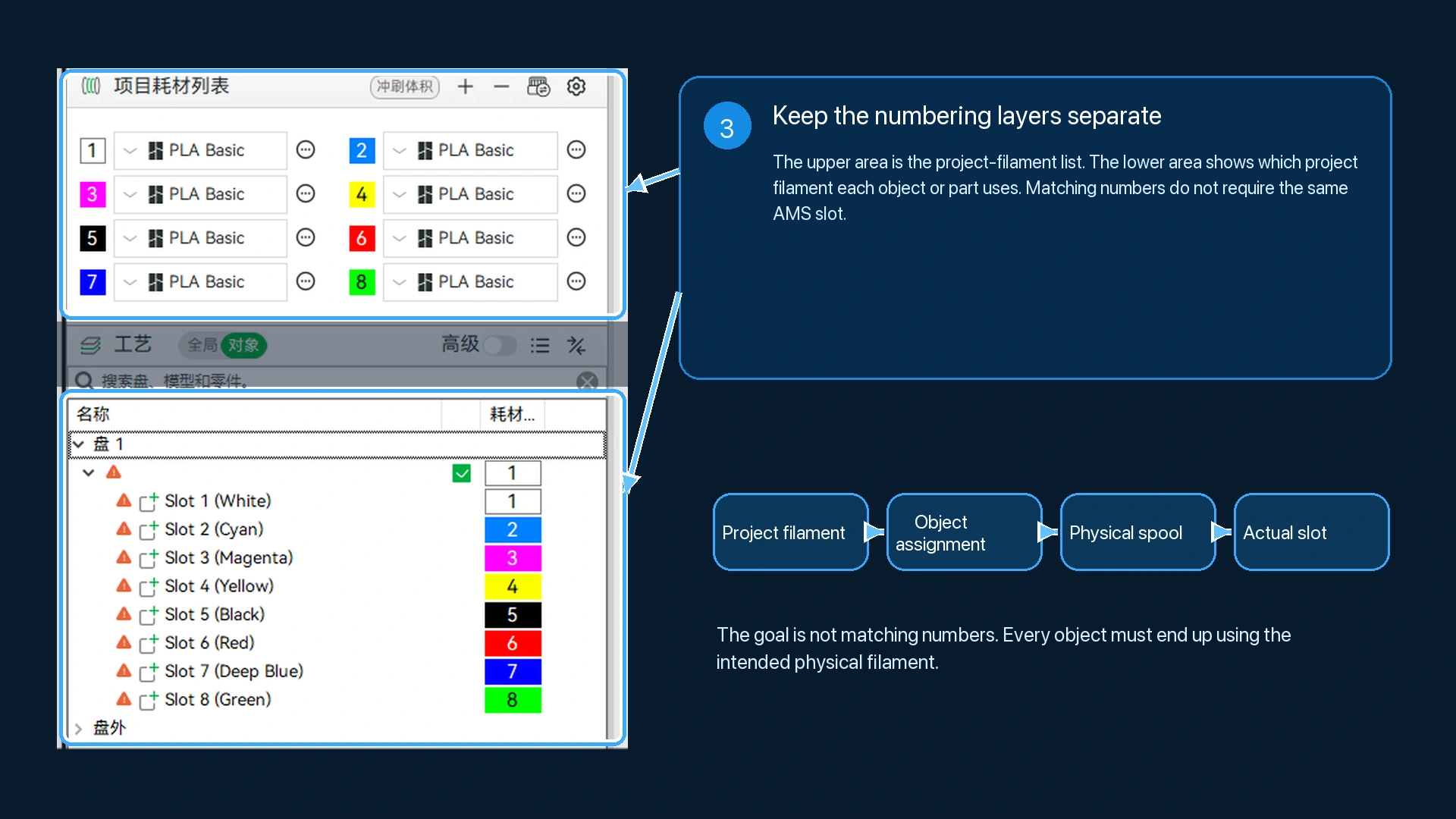
Before changing any colours, distinguish these four things:
| Information | What it represents | Where to check it |
|---|---|---|
| Project filament | The number, display colour, and material preset stored in the 3MF | The slicer's project-filament list |
| Object filament assignment | The project-filament number assigned to a particular object or part | The number or colour swatch in the object list |
| Physical filament | The real spool you intend to use, including its material, brand, and colour | The spool and its label |
| Actual slot | The AMS, other material-system, or external-spool position that currently holds that spool | The printer or material-system state and your own loading record |
For example, an object displaying 3 uses project filament 3. It does not mean that the spool must be placed in AMS slot 3. Project filament 3 can map to a different physical slot according to how you load and confirm the materials.
Likewise, a red, blue, or white swatch in the slicer mainly helps you recognise an entry. The on-screen swatch cannot prove that the printer contains the same brand, material, or physical colour.
Step 4: Check the project-filament list
Start with the project-filament list. Check that each number has a material type and display colour that broadly match the filament profiles and generated result used in Lumina.
Pay attention to the following:
- Check the material type, such as PLA or PETG, instead of looking only at colour.
- Two similarly coloured spools are not automatically interchangeable when their material or profile is different.
- Project-filament order does not need to match the AMS slot order.
- If the slicer substitutes a missing material preset, confirm that the replacement's material type and temperature range are compatible with the real filament.
If a project filament is clearly wrong, change its material preset and identification colour to the filament you will really use. This edits the project's filament definition; it does not yet change every object assignment or the physical slot in the printer.
Step 5: Check every object's filament assignment
Open the object list and expand the plate, model, objects, and parts one level at a time. Different 3MF files can have different structures. A single visible colour can be built from several geometry parts, while a base, outline, hanging loop, magnet cavity, or other auxiliary structure can be a separate object.
For that reason, these quantities do not have to match:
- The number of colours you can see in the source image.
- The number of project filaments used by Lumina.
- The number of objects or parts in the slicer's object list.
- The number of physical slots that the printer can use at once.
Select each object or part and inspect the number shown in its filament column. Confirm that the number points to the intended project filament. If it is wrong, select the correct project filament from the number or colour control.
Decide according to the physical spool that should print the region, not only the object's name. Names help identify parts, but they do not automatically change every time an assignment changes. A historical project might still contain an object named Base - White even after the actual assignment has been changed to black. The assignment and sliced preview determine the result.
After editing an object, check the model surface and the object list again. Confirm that you did not accidentally select the whole model, plate, or another part. When several parts need changing, update and verify them one at a time instead of relying on the overall thumbnail.
Step 6: Map project filaments to the physical slots
After the object assignments are correct, map the project filaments to the spools actually loaded in the printer.
For each project filament, check:
- Whether the material type matches.
- Whether the physical colour is the one required by this artwork.
- Whether that spool is actually loaded in the slot you plan to use.
- Whether an external spool has accidentally been treated as an automatic material-system slot.
You can map the slots manually. You may also use the slicer's synchronisation feature after you have confirmed that the device is online and its material state is correct. Synchronisation reads or updates device-side information; it cannot decide which artistic colour an object should use.
This tutorial does not require you to select the synchronisation control, connect a printer, or send a print. Even after synchronising, check both relationships again: object to project filament, and project filament to physical slot.
Step 7: Perform a real slice
After checking the mapping, slice the current plate. When slicing finishes, open Preview. Do not decide that the colours are correct while still on the Prepare page.
In Preview, display the paths by filament and confirm that:
- Every main region uses the intended filament.
- The base, outlines, and auxiliary structures did not move to the wrong colour.
- The slicer did not automatically substitute a material or slot.
- There are no unsliceable, floating, or out-of-bounds warnings.
If the on-screen colour is slightly different from the real spool, determine whether it is only an inaccurate display swatch or a genuinely wrong mapping. A display-colour difference alone does not necessarily change the physical filament. An incorrect object or slot mapping must be fixed before printing.
Step 8: Turn to the display surface and inspect the layers
Find the surface that will be viewed on the finished piece. If the display surface faces the build plate, turn the view to the bottom. If the artwork was deliberately designed to display from the top, inspect the top instead.
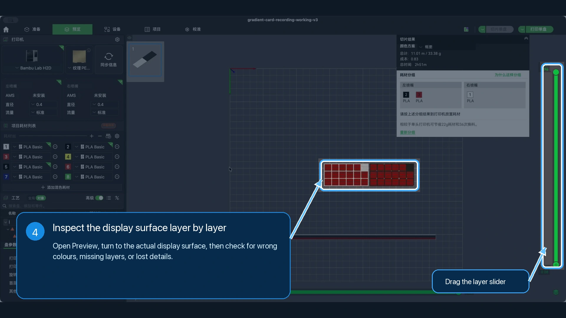
Drag the right-hand layer slider and inspect the print from the display surface one layer at a time:
- Check that the first outlines and colours appear as expected.
- Check that colour changes occur on the intended layers.
- Look for small text, thin lines, or tiny colour regions that disappeared after slicing.
- Check that the base is complete and has no unexpected holes or missing layers.
- Check that the prime tower, supports, or other auxiliary structures do not use the wrong filament.
A correct-looking model on the Prepare page does not replace a layer-by-layer preview. Only the sliced toolpaths show what the nozzle is actually preparing to print.
If a fine detail disappears after slicing, changing an AMS slot is not the solution. Reconsider the finished size, nozzle, line width, generation mode, and source-image detail before sending the job to the printer.
When the display surface, sliced layers, and physical slots are all correct, this checking workflow is complete. Whether to print immediately remains your final decision on your own device.
Troubleshooting
The original settings and colour groups disappeared after opening the 3MF
Check whether you selected an option that imports only the model or geometry. Close the current file and reopen the original 3MF as a complete project. If the project was generated for another printer or nozzle, correct the device settings in Lumina and generate it again rather than rebuilding every setting by hand.
The slicer automatically replaced a project filament with the wrong material
The local slicer may not have the original material preset, or device synchronisation may have substituted one of the currently loaded slots. Check the project-filament definition, object assignment, and physical slot separately. Changing only one layer can leave the mapping incorrect.
The artwork has only a few colours, but the object list contains many more entries
Objects are geometry, not colours. One colour can be divided into several parts, while the base, outline, hanging loop, magnet cavity, or another auxiliary structure can be its own object. Inspect each object's assignment instead of treating the object count as the colour count.
The Preview colour does not exactly match the physical spool. Will it print incorrectly?
Not necessarily. The slicer's swatch can be an approximate display colour. Confirm that the object points to the intended project filament and that the project filament maps to the intended physical spool and slot. If those relationships are correct, a display-swatch difference normally does not replace the real filament. A mapping error must still be corrected.
Small text or thin lines appear on Prepare but disappear after slicing
Prepare displays the model geometry; Preview displays the toolpaths that the nozzle can actually produce. Details smaller than the stable range of the current nozzle and line width can be merged or removed. Choose the finished size, nozzle, generation mode, and source artwork according to your own priorities instead of forcing one fixed parameter set onto every project.
Next steps
If both the preview and physical mapping are correct, continue with your normal printer workflow. For a first print, consider a smaller test piece and record the Lumina filament profiles, project-filament order, and physical slot mapping. Those notes make a later colour difference much easier to diagnose.
If the sliced preview is correct but the physical print is still visibly off-colour, check the filament profile, spool batch, first-layer condition, and viewing light before repeatedly changing object names or display swatches.
Submit feedback
Your feedback is sent privately to the Wiki maintainers and is not displayed publicly on this page.